English

Views: 0 Author: Site Editor Publish Time: 2026-09-01 Origin: Site
An air blown micro cable is a compact optical cable designed to travel through a pre-installed microduct with a cable-blowing machine and controlled compressed air. It changes the order of a fiber build: instead of opening a route every time capacity is needed, a network owner can install duct pathways first and add cable later. That makes the technology especially useful where access is difficult, capacity will grow in stages, or disruption must be limited. This guide explains the cable, duct and installation system as one engineering decision.
Air blowing is a deployment method, not simply another cable name; cable, duct, machine and route condition must match.
A microduct route can be built ahead of demand, then populated with fiber in phases.
Diameter consistency, sheath behavior, bend management and duct cleanliness affect installation performance as much as fiber count.
The method is usually most valuable where civil work is costly or future upgrades are likely.
An air-blown system normally includes a microduct, a compact cable, a blower that feeds the cable, an air source and route preparation tools. Airflow helps move the cable along the duct while the machine provides controlled mechanical feed. The objective is not to pull the cable under high longitudinal load; it is to advance it smoothly while keeping friction and compression under control.
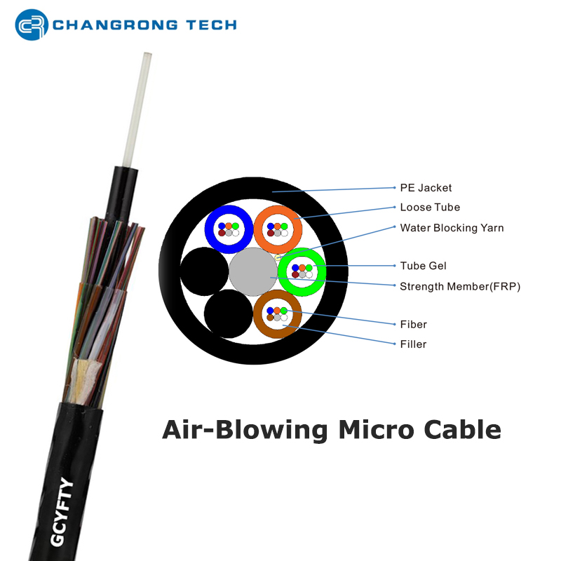
The term can cover several designs. For outdoor access and feeder work, a stranded loose-tube design protects fibers while maintaining flexibility. CROFC's GCYFTY air-blown microduct fiber optic cable is a non-metallic stranded loose-tube option for microduct laying, with FRP central reinforcement, water-blocking yarn and a PE outer sheath. Its published range covers 2 to 288 fibers, so planners can align capacity with the stage of the build instead of assuming one universal cable size.
This approach should not be confused with ordinary duct pulling. Conventional duct fiber cable may be selected when the route, protection requirement or installation practice calls for a more traditional construction. Air-blown micro cable is engineered around small ducts and pneumatic installation compatibility.
The crew first verifies that the duct route is continuous, clean and correctly jointed. A proofing or roping step can reveal crushed duct, debris, poor couplers or an unexpected restriction before the cable reaches it. The cable drum is then positioned so the cable enters the machine without twists or sharp departure angles. A blowing head seals around the selected cable and duct, while the operator controls feed, air supply and progress.
Route performance depends on the complete system. A long, straight, clean route may behave very differently from a route of the same length with repeated bends, elevation changes or duct joints. Treat quoted installation distance as project-specific evidence, not a universal promise. Before the main run, use a short representative trial to validate the actual duct, cable diameter, machine configuration and air conditions.
The installation sequence is usually:
Inspect and prove the microduct route.
Confirm cable outer diameter, fiber count, drum length and minimum bend requirements.
Fit the correct seals and feeding belt or wheel set to the blower.
Blow a test section and check speed, air loss and cable handling.
Complete the run, leave suitable end allowance, then terminate and test the optical link.
After installation, label ducts and closures clearly. The value of a microduct network lies partly in its spare pathways; unclear records can remove that advantage during the next expansion.
The fiber type must suit the network design, while the cable construction must suit the route. The published GCYFTY design can use single-mode or multimode fiber options and combines loose buffer tubes with a non-metallic strength member. Loose tubes separate fibers from routine mechanical movement; water-blocking elements help manage moisture migration; and a smooth outer sheath is intended to reduce resistance inside the duct.
Ask the supplier for the product data corresponding to the exact fiber count, not a generic family description. A practical review should cover the following:
Decision point | Why it matters | What to confirm |
|---|---|---|
Duct inside diameter | Governs usable clearance and airflow | Actual duct specification and coupler bore |
Cable diameter | Affects fit and blowing behavior | Tolerance for the selected core count |
Fiber type | Affects link design and bend behavior | Required optical specification |
Route geometry | Adds friction and handling risk | Bends, elevation, joints and access points |
Jacket choice | Determines environmental compatibility | PE or another requested construction |
For dense indoor termination segments, the cable route may eventually transition to FTTH drop cable. That does not make the products interchangeable: the feeder or distribution cable must be selected for its own pathway, protection and termination plan.
The common use case is a staged FTTx build. A developer or operator places microduct bundles during civil work, then blows fiber into only the ducts needed for an initial service area. Empty ducts remain available for a later split, new subscriber cluster or capacity increase. This is particularly helpful in urban corridors, campuses and multi-building developments where reopening surfaces creates schedule and coordination problems.
It also fits enterprise and industrial sites that need a compact pathway and a non-metallic cable construction. In these cases, selection should still begin with the installed environment. Chemical exposure, indoor fire requirements, access constraints and cable management rules can be more important than a generic “fast installation” claim. CROFC can be considered as part of the supplier evaluation because its quality-control system and product documentation give project teams a route for confirming the applicable specification before purchase.
The strongest business case is usually lifecycle flexibility. A conventional build may install a large cable because later access will be difficult. A microduct design can reserve pathways and defer some cable purchases until the demand is real. The trade-off is that the first stage needs disciplined duct design, records and installation control.
Start with a route map: identify feeder sections, distribution branches, building entries and likely growth areas. Then allocate duct capacity based on probable service stages, not only today’s subscriber count. Specify the selected air blown micro cable with the actual fiber count and drum length, and align closures, splicing and test points with the topology. Finally, agree acceptance criteria for duct integrity and optical testing before work begins.
Air-blown microduct fiber is most useful when a network needs both immediate connectivity and a practical way to grow. It is not an automatic replacement for every duct cable. The right choice comes from matching route geometry, duct dimensions, capacity plan and installation equipment to a cable designed for the system. For a project-specific construction or data sheet, contact CROFC with the route, duct details and required fiber count.
Air blown micro cable is a microduct cable specifically intended for pneumatic installation. Confirm the product's stated installation method rather than relying on a broad category label.
Yes. Reserving empty, documented microducts is one of the principal reasons to use this architecture.
Common causes include dirty or damaged duct, an unsuitable cable-to-duct fit, leaks, poor route geometry or incorrect machine setup.
Not automatically, but cable diameter changes with construction and fiber count. Check the exact product dimensions and duct clearance.
It can be a strong choice for feeder and distribution portions of an FTTH system where microduct infrastructure is planned or available.


