English

Views: 0 Author: Site Editor Publish Time: 2026-11-11 Origin: Site
Short aerial fiber routes often need a cable that is lighter and simpler than standard long-span ADSS. Urban access networks, rural broadband projects, and FTTH distribution routes usually have moderate fiber requirements and closely spaced poles. In these conditions, an oversized long-span cable may increase procurement and installation costs unnecessarily.
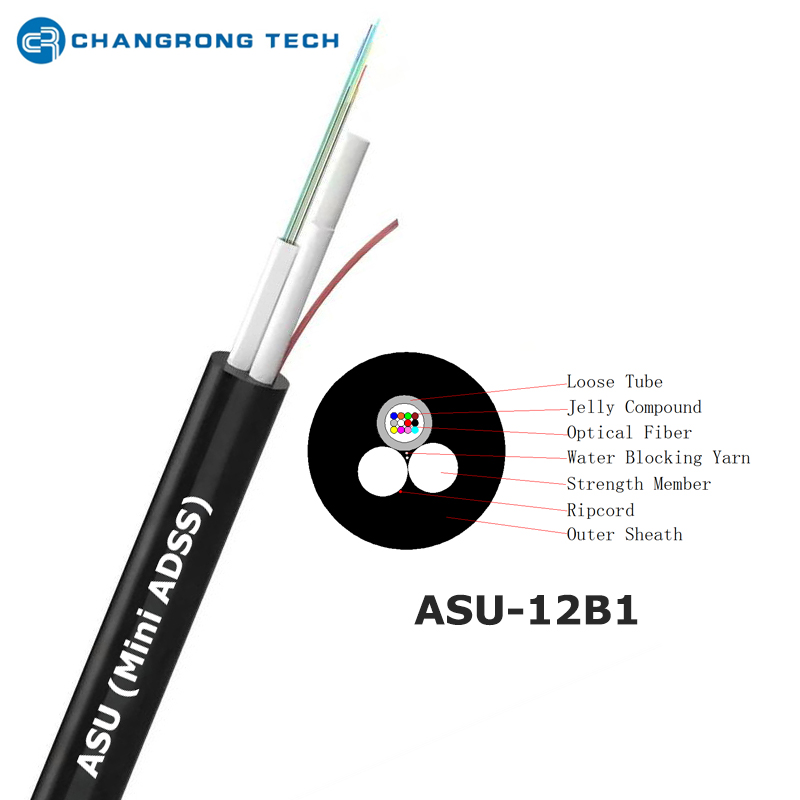
Mini ADSS (ASU) Fiber Optic Cable combines a central loose tube with two non-metallic strength members. This compact structure is commonly used for short aerial spans. This guide explains its construction, specifications, applications, limitations, and differences from standard ADSS cable.
Mini ADSS is also commonly called ASU fiber optic cable.
It usually contains one central loose tube and two parallel FRP rods.
Common nominal spans include 80, 100, 120, and 150 meters.
Typical applications include FTTH, rural broadband, CCTV, and access networks.
Standard ADSS better suits longer spans and heavier environmental loads.
Cable selection must consider wind, ice, sag, tension, and electrical exposure.
PE and anti-tracking jackets serve different installation environments.
Compatible clamps and documented testing are essential for reliable deployment.
Mini ADSS is a compact, self-supporting aerial fiber optic cable. It carries optical fibers between poles without requiring a separate metallic messenger wire.
The term ASU commonly describes a unitube aerial cable with two parallel FRP strength members. Exact structures and ratings vary, so buyers should review the technical datasheet before selection.
ADSS stands for All-Dielectric Self-Supporting. “All-dielectric” means the cable contains no metallic strength members. “Self-supporting” means its internal structure supports the cable between attachment points.
Mini ADSS applies this concept to short-span access and distribution routes. Its smaller diameter and simpler structure distinguish it from many standard ADSS designs.
ASU is commonly used as another name for this compact unitube configuration. However, the name alone does not define span capacity, tensile strength, or fiber count.
Mini ADSS cables use non-metallic materials such as FRP rods and polymer jackets. These components do not create a conductive path through the cable.
Optical fibers transmit data using light. They are not affected by electromagnetic interference in the same way as metallic communication conductors.
This dielectric construction supports deployment near electrical infrastructure. Installation crews must still follow approved clearances and power-line safety procedures.
Two FRP rods normally provide the mechanical support required for short aerial spans. They carry the cable weight and resist installation tension.
A separate steel messenger wire is not required. The route still needs compatible dead-end clamps, suspension clamps, brackets, and other attachment hardware.
The permitted span depends on cable weight, sag, wind, ice, temperature, and installation tension. Nominal span alone cannot confirm suitability.
Mini ADSS normally combines optical fibers, one loose tube, water-blocking materials, two FRP rods, and an outer jacket. The compact layout reduces cable diameter and weight.
The optical fibers sit inside a central polymer tube. This tube helps isolate them from tensile strain, bending, and temperature-related movement.
The tube may contain filling compound or dry water-blocking material. Both systems help restrict moisture movement along the cable.
The tube size depends on the required fiber count. Buyers should also confirm fiber identification, color sequence, and splicing requirements.
Two FRP rods are positioned on opposite sides of the loose tube. They provide tensile strength while maintaining the cable’s all-dielectric construction.
FRP is lightweight and corrosion-resistant. It also provides greater structural stiffness than soft aramid reinforcement.
The rod dimensions influence the finished cable diameter and mechanical rating. Their performance must be evaluated as part of the complete cable structure.
The outer jacket protects internal components from sunlight, moisture, abrasion, and handling damage. Polyethylene is commonly used for outdoor aerial applications.
Water-blocking yarns, compounds, tapes, or powders may protect the central tube. The selected system affects cable weight, splicing work, and moisture resistance.
An anti-tracking jacket may be required in stronger electrical fields. Jacket selection should follow an evaluation of the attachment location.
Mini ADSS and standard ADSS share an all-dielectric, self-supporting concept. However, their structures and intended applications differ.
Comparison Factor | Mini ADSS / ASU | Standard ADSS |
|---|---|---|
Basic construction | Central loose tube with two FRP rods | Loose tubes or central tube with aramid reinforcement |
Typical span | Short-span aerial routes | Medium- and long-span aerial routes |
Common fiber count | Usually 2–24 fibers | Can support much higher fiber counts |
Main strength element | Parallel FRP rods | Aramid yarn and dielectric strength members |
Cable size | Generally smaller and lighter | Usually larger for higher strength or capacity |
Common application | FTTH, CCTV, rural access, local distribution | Backbone, utility communication, long crossings |
Design priority | Compactness and short-span economy | Higher tensile strength and environmental resistance |
Mini ADSS is commonly offered for nominal spans of 80, 100, 120, or 150 meters. Actual suitability depends on route conditions.
Standard ADSS can support longer spans because its strength layer is designed for greater mechanical loading. It is often selected for wide pole spacing, valleys, rivers, and exposed utility routes.
Buyers should compare Rated Tensile Strength, Maximum Allowable Tension, Everyday Stress, and permitted installation tension. These values provide more useful information than a product name alone.
Mini ADSS normally carries a low-to-medium fiber count. This capacity suits neighborhood distribution, surveillance, and rural access networks.
Standard ADSS can contain multiple loose tubes and substantially more fibers. It is more appropriate for backbone routes or utility networks requiring greater capacity.
Fiber planning should consider current demand, redundancy, restoration requirements, and future expansion.
Mini ADSS uses a relatively simple structure and less reinforcement. Its smaller diameter may reduce transportation, handling, and hardware requirements.
Standard ADSS generally requires more strength material and larger accessories. These additional costs support longer spans and heavier loads.
The lower price of Mini ADSS does not make it suitable for every route. Using it beyond the intended mechanical conditions can increase maintenance and replacement costs.
Nominal span classes provide an initial reference for cable selection. They do not replace route-specific engineering calculations.
An 80-meter Mini ADSS cable commonly serves urban and residential access networks. These routes usually have relatively close pole spacing.
Typical applications include FTTH distribution, CCTV connections, and village broadband. Wind, ice, and route angles must still be considered.
A nominal 80-meter rating does not guarantee suitability for every span of that length. Environmental loading may require a stronger construction.
The 100- and 120-meter versions support routes with wider pole spacing. They retain the central unitube and parallel FRP structure.
Longer spans increase tension and sag. Cable weight and local weather become more important as the distance between supports increases.
A Mini ADSS ASU cable for 80-, 100-, or 120-meter spans can be evaluated according to the route’s actual loading conditions.
Some ASU constructions are designed for spans approaching 150 meters. Buyers should confirm the complete mechanical datasheet for these products.
At this range, standard ADSS may provide a more suitable design for exposed or heavily loaded routes. Cost should not be the only selection factor.
Mixed routes may use Mini ADSS for regular spans and standard ADSS for critical crossings.
Cable selection should be based on a complete technical datasheet. Fiber count and nominal span provide only part of the required information.
Specification | Information to Confirm | Why It Matters |
|---|---|---|
Fiber count | Active fibers and expansion margin | Determines network capacity |
Fiber type | Applicable single-mode or multimode standard | Affects transmission performance |
Nominal span | Required distance between supports | Guides mechanical selection |
Cable diameter | Finished outside diameter | Determines clamp and pulley compatibility |
Cable weight | Weight per kilometer | Influences sag and structural loading |
Tensile values | RTS, MAT, EDS, and installation tension | Protects cable from mechanical overload |
Bend radius | Static and dynamic requirements | Reduces fiber and tube damage |
Temperature range | Installation, operation, and storage limits | Supports environmental reliability |
Jacket material | PE or anti-tracking compound | Matches outdoor and electrical exposure |
Test requirements | Optical, mechanical, and environmental tests | Supports quality verification |
Cable diameter depends on fiber count, tube size, FRP dimensions, and jacket thickness. It directly affects clamp and pulley selection.
Cable weight influences sag, tension, and support loading. Route calculations should use the value shown on the final datasheet.
The fiber count should include a reasonable expansion margin. Excessive spare capacity can increase size and splicing requirements unnecessarily.
Mechanical specifications should include short-term and long-term tensile values. Buyers should also request the permitted installation tension.
Sag changes with span, temperature, wind, and ice. The manufacturer should provide suitable sag-tension information for installation.
A cable should not be tensioned using a general percentage taken from another product. Each construction has its own limits.
The required operating range should reflect local seasonal temperatures. Separate storage and installation limits may also apply.
Wind creates lateral pressure and vibration. Ice adds weight and increases tensile loading.
Local design data should be included in the RFQ. Combined wind-and-ice conditions may control the final cable selection.
The cable jacket protects the internal structure from outdoor exposure. Its electrical performance is especially important near energized conductors.
A polyethylene jacket provides resistance to ultraviolet exposure, moisture, and abrasion. It is commonly used on telecom poles and lower electrical-stress routes.
PE suitability depends on the actual attachment location. Transmission-line voltage alone does not define the cable’s electrical exposure.
Pollution, humidity, and conductor arrangement should also be evaluated.
An anti-tracking jacket is designed to resist surface tracking and dry-band arcing. It may be required near medium- or high-voltage conductors.
The electrical space potential can vary between attachment positions on the same structure. Therefore, jacket selection should follow an electrical-field assessment.
An anti-tracking jacket should not replace required installation clearances or safety procedures.
Ultraviolet radiation, temperature, moisture, and contamination affect long-term jacket performance.
Coastal salt, industrial emissions, and agricultural dust can increase surface contamination. These conditions should appear in the project specification.
Buyers should request relevant jacket-aging and environmental test information when needed.
Mini ADSS mainly serves access and distribution networks with moderate fiber demand and short pole spacing.
Mini ADSS can connect fiber distribution points across residential communities. Its compact size suits aerial FTTH distribution routes.
The cable can be installed without a separate messenger wire. This reduces the number of components required along suitable pole routes.
Individual subscribers are normally connected through separate drop cables after the distribution stage.
Existing poles can provide practical routes for rural fiber deployment. Mini ADSS can connect villages, schools, clinics, and distribution cabinets.
Short-span ASU cable may suit sections with closely spaced poles. Longer or exposed crossings may require standard ADSS.
Route planners should evaluate pole condition, vegetation, weather, access, and maintenance requirements.
Mini ADSS can connect outdoor cameras, traffic-monitoring devices, buildings, and industrial facilities.
Optical transmission supports long-distance video and data links. The dielectric construction also performs well near electrical equipment.
Fiber capacity should include planned cameras, sensors, access points, and redundant connections.
Distribution networks may use Mini ADSS to connect meters, switches, sensors, and local control devices.
Short pole spans and moderate fiber counts can match ASU cable characteristics. Attachment positions and electrical exposure still require technical assessment.
The broader ADSS Fiber Optic Cable range can be considered when one route contains different span and capacity requirements.
Mini ADSS provides clear advantages within its intended application range. Its limitations should also be considered during route planning.
The unitube structure and parallel FRP rods create a relatively small cable profile. This can simplify transportation and handling.
Lower weight may reduce additional pole loading. Existing structures should still be inspected before deployment.
Compact dimensions are especially useful on access routes with limited attachment space.
The cable does not require a separate metallic messenger. This can reduce material and installation steps.
Its smaller size may allow the use of compact clamps and installation tools. Hardware must still match the finished cable diameter.
Cost efficiency depends on correct cable selection. An underspecified cable can create far higher repair costs.
Mini ADSS is normally intended for shorter spans than standard ADSS. Heavy wind, ice, or large route angles may exceed its mechanical capacity.
The unitube structure also limits the practical fiber count. Backbone networks may need greater capacity.
Standard ADSS should be considered when a project requires longer spans, higher fiber counts, or heavier environmental loading.
Proper handling protects the optical fibers, loose tube, FRP rods, and outer jacket.
The route survey should identify span lengths, pole conditions, route angles, crossings, attachment heights, and electrical clearances.
Wind, ice, vegetation, and installation access should also be documented. This information supports cable, hardware, and reel-length planning.
Critical spans should be identified separately. They may require a different cable construction.
Installation crews should follow the manufacturer’s sag-tension information. Excessive tension can damage fibers or strength members.
Insufficient tension may create excessive sag and clearance problems. Installation temperature should be included in the calculation.
Pulleys, cable guides, and storage brackets must maintain the specified bend radius.
Dead-end clamps anchor the cable, while suspension clamps support intermediate points. Both must match the cable diameter and mechanical rating.
Cable reels should remain upright and secured during transportation. Cable ends should stay sealed against moisture.
The cable must not be kinked, crushed, dragged, or pulled beyond the permitted tension.
A detailed RFQ helps manufacturers prepare accurate and comparable quotations.
Buyers should provide:
Fiber count, fiber type, and attenuation requirements
Individual spans, sag limits, wind, ice, and temperature
Electrical conditions and required jacket material
Hardware types, quantities, reel lengths, and delivery terms
Applicable testing standards and required documentation
Vague terms such as “long span” or “heavy wind” should be replaced by measurable values.
Optical tests may include attenuation, fiber continuity, length verification, and OTDR traces.
Mechanical tests may cover tensile strength, crushing, impact, bending, and torsion. Environmental testing can include temperature cycling and water penetration.
The purchase specification should define both test methods and acceptance values.
Buyers may request product datasheets, cable drawings, type-test reports, routine test records, and reel-specific optical results.
Pre-shipment inspection requirements should be agreed before production. They can affect delivery schedules and commercial quotations.
Certification claims should be verified through applicable documents rather than assumed from general marketing descriptions.
Mini ADSS, also known as ASU cable, provides a compact solution for short-span aerial fiber networks. Its central tube, parallel FRP rods, and dielectric construction suit FTTH, rural broadband, CCTV, campus, and smart-grid applications.
Its smaller diameter and lower weight can simplify short-route deployment. However, cable selection must still consider span, sag, wind, ice, temperature, fiber count, and electrical exposure.
Standard ADSS remains more suitable for long spans, large fiber counts, and demanding environmental loads. Mixed routes may use both cable types to balance performance and cost.
The CROFC ADSS Cable range includes Mini ADSS and other aerial cable configurations. Final selection should follow route calculations and confirmed project specifications.
The terms are commonly used for the same compact aerial unitube design. It normally has one central loose tube and two parallel FRP rods.
Actual span, fiber count, and tensile performance depend on the specific product construction.
Common nominal spans include 80, 100, 120, and 150 meters. These values are product references rather than universal limits.
Wind, ice, cable weight, sag, and installation tension must also be evaluated.
Mini ADSS can be installed near power infrastructure when its jacket, attachment position, and mechanical design match the route.
An anti-tracking jacket may be required under stronger electrical fields. Approved utility safety procedures remain necessary.
Mini ADSS normally uses parallel FRP rods for short-span access networks. Standard ADSS commonly uses aramid reinforcement for longer spans and heavier loads.
Standard ADSS can also support higher fiber counts. The final choice should reflect route and network requirements.


