English
Views: 0 Author: Site Editor Publish Time: 2026-03-24 Origin: Site
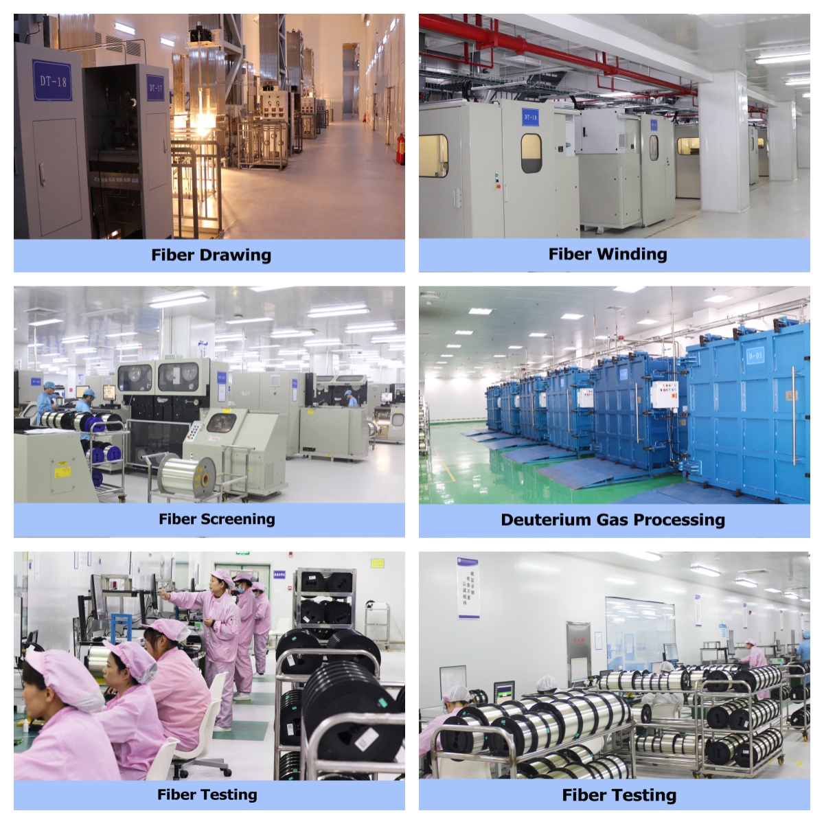
Optical fiber drawing is a continuous precision process that melts a preform at high temperature, draws it into micron-scale bare fiber, and applies protective coating. Before delivery, four categories of tests (geometric, optical, mechanical, environmental) are conducted to comply with ITU‑T/IEC standards.

Cleaning: Remove impurities with hydrofluoric/nitric acid, rinse with pure water, dry with nitrogen
Stub Connection: Weld glass stub by oxy-hydrogen flame on glass lathe, polish, clean and seal
Loading: Vertically clamp onto the feeding mechanism at the top of the drawing tower
Heating: Graphite furnace at 1850–2200°C to melt the bottom of the preform
Feeding & Traction: Closed-loop control of preform feed speed and traction speed to form 125 μm cladding diameter
Real-time Diameter Monitoring: Laser diameter gauge (accuracy ±0.1 μm) adjusts speed dynamically
Cooling: Rapid cooling to room temperature with helium & air to form solid bare fiber
Annealing: Heat preservation at 1000–1100°C to eliminate internal stress and reduce attenuation
Primary Coating: High-modulus acrylate, UV cured, approx. 245 μm diameter
Secondary Coating: Soft buffer layer, UV cured; 250 μm (tight buffered) / 900 μm (loose buffered)
Diameter & concentricity inspection for coating layers
Tension Control: Real-time monitoring to avoid breakage and ensure mechanical strength
Winding: Constant-tension winding onto fiber spools
Online Screening: 1% strain tension screening to eliminate weak fibers
Item | Typical Value (G.652.D) | Standard | Instrument |
|---|---|---|---|
Cladding Diameter | 125.0±1.0 μm | IEC 60793‑2‑50 | Laser Diameter Gauge |
Core/Cladding Concentricity Error | ≤0.5 μm | ITU‑T G.652 | Interferometer / Microscope |
Cladding Non-circularity | ≤0.5% | IEC | Laser Diameter Gauge |
Mode Field Diameter (MFD) | 9.2±0.5 μm | ITU‑T G.652 | Far/Near Field Scanner |
Coating Diameter | 250±10 μm | Enterprise Standard | Diameter Tester |
Item | Typical Value (G.652.D) | Standard | Instrument |
|---|---|---|---|
Attenuation Coefficient | ≤0.36 dB/km @1310 nm ≤0.22 dB/km @1550 nm | ITU‑T G.652.D | OTDR / Optical Power Meter |
Cut-off Wavelength | ≤1260 nm | ITU‑T G.652 | Cut-off Wavelength Tester |
Chromatic Dispersion | ≈0 @1310 nm ≈17 ps/(nm·km) @1550 nm | ITU‑T G.652 | Dispersion Analyzer |
Polarization Mode Dispersion (PMD) | ≤0.20 ps/√km | ITU‑T G.652 | PMD Analyzer |
Macro-bend Loss | ≤0.1 dB (100 loops, 15 mm radius) | ITU‑T G.652 | Bend Loss Tester |
Item | Requirement | Standard | Instrument |
|---|---|---|---|
Tensile Strength | Breaking load ≥5.3 N (0.5% strain) | IEC 60793‑1‑30 | Tensile Tester |
Proof Test Tension | 1% strain (6–8 N approx.) | Industry Specification | Tension Screening Machine |
Repeated Bending | No crack after 50 cycles (20D bending) | IEC | Bending Tester |
Crush Resistance | Attenuation change ≤0.05 dB under 3000 N / 10 min | IEC | Crush Tester |
Temperature Cycling: -40°C ↔ +70°C, 10 cycles; attenuation variation ≤0.05 dB/km
Damp Heat: 85°C / 85% RH, 1000 hours with stable performance
Hydrogen Aging: Stable attenuation under 80°C & 1% hydrogen atmosphere
Water Immersion: No obvious attenuation change after immersion
Geometry: Laser scanning, interferometry, image analysis (IEC 60793‑2‑50)
Optics: Cut-back method, OTDR backscattering, phase-shift method (dispersion)
Mechanics: Proof screening, tension, bending & crush tests (IEC 60793‑1‑30/40/47)
Environment: GB/T 2423, IEC 60793‑1‑53, Telcordia GR‑20
9 cutting-edge fiber drawing towers, 2 lines per tower, totally 18 production lines
Drawing speed: 2800 m/min
Annual output 15,000,000 (15 million) km if full capacity
Fiber types: single-mode fiber G652D, G657A1, G657A2
Standard reel length: 24.4 km, 48.8 km, 50.4 km


