English
Views: 0 Author: Site Editor Publish Time: 2026-05-27 Origin: Site
Outdoor fiber networks now span cities, farms, and factories. Cable structure directly affects speed, cost, and reliability. Self-supporting FIG8 Aerial Fiber Cable simplifies aerial deployment and reduces hardware needs. In this article, you will learn how it compares with traditional aerial fiber cables and which option fits different projects.

● Self-supporting Figure 8 Aerial Fiber Cable combines the optical cable and messenger wire into one compact structure. It speeds up installation and lowers labor costs.
● Traditional aerial fiber cables rely on separate messenger strands and lashing hardware. They still work well in some legacy or short-span networks.
● Figure 8 cable designs offer better tensile strength and improved sag control during long-span outdoor deployments.
● UV-resistant jackets, armored structures, and water-blocking materials help improve long-term outdoor durability.
● Telecom providers and contractors often choose integrated Figure 8 cables for rural broadband and industrial networks because they reduce installation complexity.
● Traditional aerial systems may remain useful when existing support strands already exist or custom routing is needed.
● Choosing the correct cable depends on span length, climate conditions, fiber count, and future network expansion plans.
The Unique Figure 8 Cable Structure
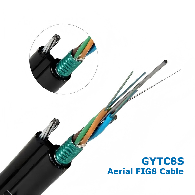
A Self-supporting Figure 8 Aerial Fiber Cable combines the optical fiber core and support messenger into one integrated design. The cross-section looks like the number eight, which gives the cable its name. This design removes the need for separate support strands during installation.
The messenger wire sits above the optical cable section. It carries tensile loads during aerial deployment. Installers can pull and suspend the cable faster because both parts come as one unit.
Some designs use steel messenger wires for higher tensile strength. Others use non-metallic materials for lighter weight and better lightning resistance. Each option suits different environmental conditions.
Tip: Integrated messenger structures reduce installation hardware and improve deployment efficiency on long pole routes.
Key Components Inside Self-supporting Figure 8 Aerial Fiber Cable
Most Figure 8 cables use loose tube fiber construction. The fibers stay protected inside gel-filled or dry water-blocking tubes. This design helps prevent moisture damage during outdoor use.
Manufacturers also add water-blocking yarns or tapes. These materials stop water migration if the outer sheath gets damaged.
Many outdoor aerial cables include armored layers. Steel tape or aluminum armor protects against crushing pressure and rodents. This matters in rural and industrial areas.
The outer sheath usually uses UV-resistant polyethylene. It resists sunlight, rain, and temperature changes for years.
Component | Function |
Messenger wire | Supports tensile load |
Loose tube | Protects optical fibers |
Water-blocking layer | Prevents moisture entry |
Armored layer | Resists impact and rodents |
PE outer sheath | Protects against UV and weather |
How Traditional Aerial Fiber Optic Cables Are Built
Traditional aerial fiber optic cables normally require separate support systems. Contractors first install a messenger strand between utility poles. Then they lash the fiber cable onto the strand using lashing wire.
This process needs extra hardware, including clamps, lashers, suspension devices, and tension accessories. Installation often takes longer because crews handle multiple components separately.
Although traditional systems remain common, they usually increase labor intensity during large projects.
Note: Separate lashing systems may create additional maintenance points over long operating periods.
Common Deployment Scenarios
Self-supporting Figure 8 cables perform well in long-distance telecom routes, rural broadband projects, industrial parks, and campus networks. Their integrated structure simplifies outdoor deployment across wide areas.
Temporary aerial installations may still use conventional cables if existing support strands already exist. Permanent telecom infrastructure, however, often benefits from integrated cable systems.
Structural Design Comparison
The largest difference lies in the support method. Figure 8 cables integrate the messenger wire directly into the cable body. Traditional aerial systems separate the fiber cable from the support strand.
Integrated designs distribute weight more evenly. They also reduce cable movement during wind exposure. Traditional systems may allow more vibration between the cable and messenger.
Compact Figure 8 profiles also reduce clutter on utility poles.
Installation Complexity and Labor Requirements
Figure 8 cable installation usually follows a one-step process. Crews pull and secure the cable directly between poles. This reduces deployment time significantly.
Traditional systems require messenger installation first. Then crews lash the cable afterward. More hardware means more labor hours.
Factor | Figure 8 Cable | Traditional Aerial Cable |
Messenger structure | Integrated | Separate |
Installation speed | Faster | Slower |
Hardware demand | Lower | Higher |
Labor cost | Lower | Higher |
Pole space usage | Compact | More crowded |
Tip: Faster deployment helps telecom contractors reduce project delays and equipment rental costs.
Mechanical Strength and Span Performance
Self-supporting Figure 8 cables usually offer strong tensile performance across medium and long spans. Their messenger wires support higher mechanical loads during wind and ice conditions.
Traditional aerial systems can also support long spans, but performance depends heavily on correct messenger installation and lashing quality.
Figure 8 cables often show better sag control because the integrated structure reduces uneven tension distribution.
Environmental Protection Capabilities
Outdoor aerial networks face moisture, sunlight, temperature changes, and mechanical stress. Figure 8 cables typically include UV-resistant jackets and water-blocking materials for harsh conditions.
Armored versions improve resistance against rodents and accidental impacts. Coastal regions and industrial environments especially benefit from these protections.
Traditional aerial cables may achieve similar durability, but only if installers use compatible support and protection systems.
Maintenance and Long-term Reliability
Integrated Figure 8 designs simplify maintenance because there are fewer external parts. Inspectors can identify damage faster during routine checks.
Traditional lashing systems introduce additional failure points. Loose lashing wires or messenger strand corrosion may affect long-term stability.
Most high-quality Figure 8 cables support service lives exceeding 20 years under proper installation conditions.
Cost Comparison: Initial vs. Long-term Investment
Traditional aerial systems sometimes appear cheaper initially if existing messenger strands already exist. However, labor costs often increase due to longer installation time.
Figure 8 cables may cost more per meter, but they reduce labor and hardware expenses. Long-term maintenance costs also tend to stay lower.
Cost Area | Figure 8 Cable | Traditional Cable |
Cable cost | Moderate | Lower |
Hardware cost | Lower | Higher |
Installation labor | Lower | Higher |
Maintenance cost | Lower | Moderate |
Total lifecycle value | Higher | Moderate |
Which Cable Type Offers Better Overall Efficiency?
For new aerial deployments, Self-supporting Figure 8 Aerial Fiber Cable usually offers better overall efficiency. Telecom operators value its faster installation, strong mechanical performance, and lower maintenance needs.
Traditional aerial cables still make sense in legacy systems or short-distance projects where messenger infrastructure already exists.
The final choice depends on budget, deployment speed, environmental conditions, and long-term operating goals.
Reduced Installation Time
Integrated cable structures simplify pole-to-pole deployment. Crews need fewer installation steps and less equipment.
Large rural broadband projects benefit greatly from faster installation because labor availability often remains limited in remote regions.
Superior Mechanical Durability
Figure 8 cables handle high tensile stress effectively. Their messenger structures support stable aerial performance during strong wind and ice loading.
Armored designs also improve resistance against external impacts and accidental compression.
Note: Long-span aerial routes should always include proper tension calculations before deployment.
Better Adaptability for Outdoor Harsh Environments
Outdoor telecom networks face rain, sunlight, humidity, salt air, and temperature shifts. Figure 8 cables resist these conditions through durable sheath materials and water-blocking designs.
Industrial parks and coastal regions especially benefit from corrosion-resistant construction.
Space-saving and Cleaner Cable Management
Integrated cables reduce clutter on utility poles. Fewer accessories create cleaner routing paths and easier maintenance access.
This also helps maximize limited aerial infrastructure space in crowded urban areas.
Existing Messenger Infrastructure Already Installed
Many legacy telecom networks already contain support strands. Operators may reuse them during network upgrades to reduce material costs.
This approach works well when the messenger structure remains in good condition.
Short-distance or Low-load Applications
Short aerial routes may not require integrated messenger systems. Budget-sensitive projects sometimes choose traditional cables because mechanical demands remain low.
Low-wind regions also reduce the need for heavy-duty support structures.
Specialized Network Configurations
Some networks require customized support spacing or unusual routing paths. Traditional aerial systems allow more flexibility because installers can adjust messenger components separately.
Evaluate Span Length and Tensile Requirements
Longer spans require stronger messenger support. Engineers must calculate wind loads, ice accumulation, and cable tension before selecting a cable type.
Ignoring tensile requirements may cause excessive sag or structural failure.
Consider Armor Type and Environmental Risks
Rodent-prone regions benefit from armored cable designs. Industrial environments may also require stronger impact protection.
Non-metallic structures help reduce electromagnetic interference near power systems.
Tip: Match cable armor and sheath materials to the local climate and environmental hazards.
Assess Fiber Count and Future Scalability
Fiber demand continues growing due to 5G, FTTH, and smart infrastructure expansion. Choosing slightly higher fiber counts today may reduce future replacement costs.
Scalable network planning supports long-term operational efficiency.
Verify Compliance and Outdoor Performance Standards
Reliable manufacturers perform tensile testing, crush testing, water penetration testing, and temperature cycling tests. Buyers should verify compliance before purchasing.
High-quality production standards directly affect long-term cable reliability.
Rural Broadband and FTTH Networks
Rural broadband projects often involve long aerial spans across difficult terrain. Figure 8 cables reduce installation complexity and lower labor costs.
They also speed up broadband expansion into underserved communities.
Telecom Backbone Networks
Large telecom systems require stable high-capacity transmission. Figure 8 aerial cables support backbone deployments through reliable mechanical performance.
Many operators use them for regional and intercity connections.
Industrial and Utility Communication Systems
Power utilities use aerial fiber networks for monitoring and communication systems. Industrial parks also depend on reliable data transmission between facilities.
Strong outdoor durability makes Figure 8 cables suitable for these demanding environments.
Security and Smart City Infrastructure
Cities increasingly deploy surveillance cameras, traffic monitoring systems, and smart infrastructure sensors. Figure 8 cables support these networks through stable outdoor connectivity.
Demand for Faster and Easier Deployment
Broadband expansion projects continue increasing worldwide. Telecom providers now prefer integrated cable solutions because they reduce installation time and labor requirements.
Lightweight Yet High-strength Cable Innovations
Manufacturers continue developing lighter materials without sacrificing tensile strength. Improved cable design reduces pole loading while maintaining durability.
Expansion of High-density Fiber Networks
5G and smart city infrastructure require higher fiber counts. Future aerial cables will likely support larger capacities in smaller cable diameters.
Sustainability and Lower Maintenance Infrastructure
Operators increasingly focus on long-life infrastructure. Durable outdoor materials help reduce maintenance frequency and replacement costs over time.
Note: Sustainable cable systems help telecom providers reduce total operational expenses over the network lifecycle.
Self-supporting Figure 8 Aerial Fiber Cable offers faster installation, strong outdoor durability, and lower maintenance than traditional aerial systems. CROFC provides reliable aerial fiber solutions designed for telecom, industrial, and broadband networks. Its products help operators improve deployment efficiency while supporting long-term outdoor performance.
A: It is an aerial fiber cable with an integrated messenger wire for pole installation.
A: It reduces labor, speeds deployment, and improves outdoor durability.
A: Yes. It supports long spans and lowers installation complexity.
A: Yes. They work well in existing messenger strand systems.
A: Yes. It uses UV-resistant and water-blocking protection.
A: Figure 8 cable usually lowers maintenance and labor costs.


